Phased Array Ultrasonic Testing (PAUT)
Introduction
Phased Array is the ability to modify the characteristic of an acoustic probe by beam forming with help of software. This is done by time shifting the signal sent (pulse) and received (echo) to and from each element of a multi-element probe. Any UT technique for detection and sizing could be performed using Phased Array probes instead of conventional probe with great advantages.
Benefits
- PAUT is a well-established technique and recognized by many international codes (ASME, API, BSI, EN etc.) as a replacement to Radiography during construction activities.
- Inspection of difficult configurations .
- Indication height sizing helps for ECA analysis.
- Better signal to noise ratio.
- High probability of detection
- Data image can be presented in A-Scan, B-Scan (Side-view), C-Scan (Top-view), D-Scan (End-view) and S-Scan for better understanding and indication location and orientation.

Application
Weld Inspection from 0.84” and above.In-Service and Fabrication weld inspection of
- CS/LAS Material
- Corrosion-Resistant Alloy (CRA).
- Stainless steel.
- Dissimilar Welds & Clad Material
Corrosion Mapping
Hydroform Corrosion Mapping
Features
- Inspection range above 4” OD with near surface resolution of 3 mm
- Applicable up to surface temperature of 90℃
- Offers high resolution and fast coverage, with a 60 mm wide effective beam and can scan at a speed up to 100mm/s.
- Maximum data acquisition Resolution 1 mm X 1 mm.
- CSV file data export.

Rexoform Corrosion Mapping
Features
- Inspection range above 4” OD with near surface resolution of 3 mm.
- Offers high resolution and fast coverage, with a 57 mm wide effective beam and can scan at a speed up to 100mm/s
- Data acquisition Resolution 1 mm X 1 mm
- Smaller, lighter, and perfect for limited access areas (rope access).
- Operates without the need for a continuous water supply. Complement to the HydroFORM
- CSV file data export.
Dual Linear Array Corrosion Mapping
Features
- Near-surface detection capability of 1 mm (0.04 in.)
- Can be used up to 150℃ Surface Temperature
- Quick adjustment system adapts to diameters from 2” in. to flat
- Beam coverage width of up to 32 mm (1.26 in.). Offers high resolution data acquisition (1 mm X 1 mm), with a 30mm wide effective beam
- Detects mid-wall damage such as hydrogen induced blistering or manufacturing induced laminations and easily differentiates these anomalies from loss of wall thickness
- Smaller, lighter, and perfect for limited access areas (rope access)
- CSV file data export

Dis-Bonding detection in cladding & Lamination check
Depending on the item under inspection Hydroform, Rexoform or Dual Linear Array probe can be used for the inspection to detect, locate and size the Clad Dis-bond or Lamination.
In-Service Flange & Bolt Inspection
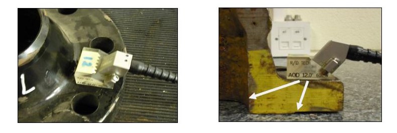
Application of Phased Array for In-service Inspection of Flange and Bolts provides data for advance planning and potentially reduces shutdown schedule. Also, helps in Remaining Life Assessment with Fracture Mechanic Approach i.e. Fitness for the Purpose (lesser repair);
Detection of HIC, SCC, SOHIC,HTHA
Due to multiple range of desired angle PAUT has high probability of detection for HIC, SCC, SOHIC and HTHA type of in-service induced indications. Combination of PAUT and manual UT and reveal the indications to the greater degree of reliability.
Flange and Bolt inspection
Introduction

There is a growing interest within the petrochemical and associated industries for the in-service inspection of flanges to identify corrosion on the flange face. Currently the majority of inspection of flanged joints is undertaken by periodically breaking the flange and visually inspecting the condition of the sealing faces. This is not only time consuming but also requires the shutdown of the system. Therefore, a reliable method of in-service inspection of flanges, without the need` to break them open, would represent a significant cost saving to all major oil and gas providers.
The in-service inspection of flanged joints is a considerable issue for the ongoing integrity of hydrocarbon processing facilities. A flanged joint consists of two mating flanges with a sealing mechanism (gasket or O-ring) between them. These joints are a break in the continuity of a line and present a route for loss of containment in the form of leakage. Loss of containment in hydrocarbon, high pressure gas or high pressure water systems is a significant safety issue and effective inspection strategies are essential to ensure the integrity of the joints at all time. There are two flange types commonly used on plant; Welded Neck (WN) Raised Face and Welded Neck (WN) Ring type joints (RTJs) and these are shown in the figure below. This paper is concerned with raised face flanges only.
The crevice created on the inside diameter of a flanged joint presents an inherent location for localized corrosion to occur. Carbon steel flanges are particularly susceptible to such attack. Over time, the corrosion of the flange face may extend into the gasket mating area potentially compromising the seal integrity of the flanged joint. Several factors can influence the rate at which the flange face may corrode. The inspection frequency of flanged joints should consider the respective corrosion rate in conjunction with the calculated sealing surface requirements.
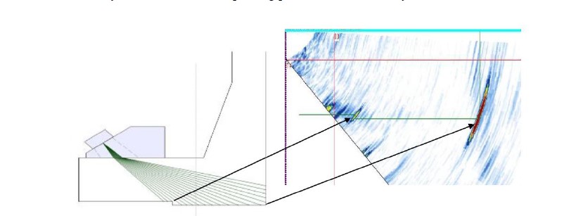
Phased Array has the ability to simultaneously collect A-scan data at a number of given angles.
This unique feature produces a volumetric beam allowing operators to distinguish between geometric reflectors and defect signals and therefore increasing the likelihood of detection (see figure 4). In addition, this ability also improves flexibility on complex geometries as the beam can be controlled to suit the requirements of the inspection. PAUT was driven by inspection problems that were unachievable with conventional methods of Non-Destructive Testing (NDT). Typical applications included [4]: -
- Crack detection at varying depths and orientations
- Improving signal-to-noise (SNR) for the inspection of dissimilar metal welding
- Encoded scanner capability
- Reduction of on-site radiography
- Detection of stress corrosion cracking (SCC) in complex geometry cast components
Bolt Inspection
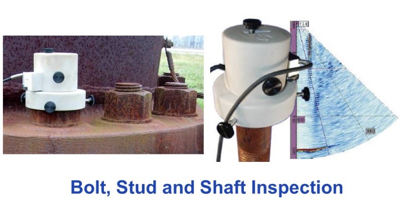
Phased arrays can be used for detecting cracking (and other defects) in high tensile bolts. The technique uses a “fingerprinting” approach to the bolts. In contrast to current code procedures where an operator manually scans a normal beam probe over a bolt and interprets the results, this phased array technique uses an S-scan and a mechanized scanner. Specifically, the phased array probe is mounted in contact on the head of the bolt, and performs a small angle longitudinal wave S-scan down the bolt. The array is mounted in a mechanized and encoded jig for 360 rotation round the bolt. Signals are received from the threads, bolt geometry and from mode conversions. In essence, the S-scan gives a fingerprint of the bolt at all depths and orientations when the operator scans round the bolt collecting data. Any perturbations from defects or cracks are typically very visible. Interpretation is much simpler than with alternative bolt inspection techniques. Some examples from calibration and cracked bolts will be shown. The technique can be fine-tuned for different bolt dimensions and features.