Tube Inspection
Introduction
Inspection of installed tubes in Heat Exchangers/ Boilers during Plant shutdown/ Maintenance overhaul
Inspection of tubes using suitable techniques (Eddy Current /Remote Field Testing/ Magnetic Flux Leakage/IRIS) for detection/sizing of damage mechanisms (corrosion, wastage, leaks and cracks) in heat exchanger/ Boilers. Inspection provides information on damage trends and extent of tube wall loss.
Internal Rotary Inspection System (IRIS) 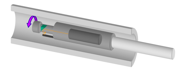
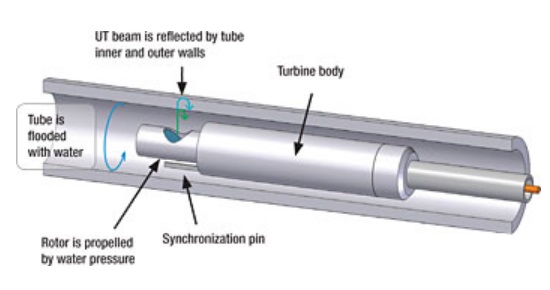
Introduction
IRIS is an ultrasonic immersion technique. Tubes under test is flooded with water as a coupling medium between sound and the part under inspection. IRIS relies on a transducer to generate an ultrasonic pulse parallel to the axis of the tube under test. It also relies on a rotating mirror that directs the ultrasonic wave into the tube wall. The mirror is driven by a small turbine powered by the pressure of water pum ube.
Application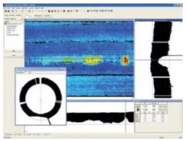
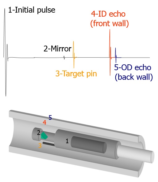
- Examine ferrous and non–ferrous tubes.
- Tubing in feed–water heaters, heat exchangers, boilers.
- Tube ID: 9.0mm – 76.2mm & Thickness: 0.7 – 6.0mm
- Piping OD: 88.9 mm – 168.3 mm & 3.05 mm – 10.97 mm
Benefits
- Can detect sharp and gradual defects but not cracks
- It can accurately measure remaining wall thickness (0.1mm).
- Equally sensitive to ID & OD defects.
- Inspection, typically 70–80 tubes per shift.
- Outside defect detection limited in finned tube
- Sensitivity – 1.5 mm diameter, 5% loss (variable with tube size / cleanliness)
- Computerized analysis.
- Inspection of partially scaled tubes and boiler tubes with swages & bends.
- Calibration tube required
- Bore surface must be very clean
Eddy Current Testing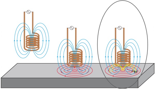
Introduction
Eddy current testing is a noncontact method used to inspect non–ferromagnetic tubing. Two coils are excited with an electrical current, producing a magnetic field around them. The magnetic fields penetrate the tube material and generate opposing alternating currents in the material. These currents are called eddy currents.
Any defects that change the eddy current flow also change the impedance of the coils in the probe.
These changes in the impedance of the coils are measured and used to detect defects in the tube.
Application
- Non – ferromagnetic tubes
- Tubing in condensers, feed–water heaters, boilers, and heat exchangers
- Tube OD: 9.53 mm to 50.8 mm
- Tube Thickness: 0.56 mm to 3.4 mm
- Bends can be tested using custom probes
Benefits
- Can detect sharp and gradual defects including cracks
- Detecting internal external defects as well as defects under support plates
- Inspection, typically 400 to 500 tubes per shift
- Cleanliness is less critical than IRIS
- Computerized analysis
- Calibration tube required
- Defects close to the tube sheet are difficult to detect
Remote Field Testing (RFT)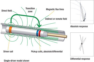
Introduction
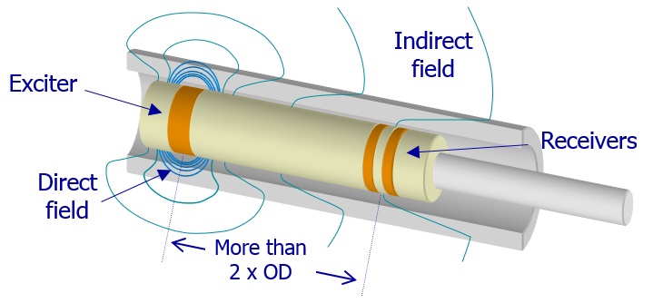
RFT is primarily used to inspect ferromagnetic tubing since conventional eddy current techniques have difficulty inspecting the full thickness of the tube wall due to the strong skin effect in ferromagnetic materials. The degree of penetration can, in principle, be increased by the use of partial saturation eddy current probes, magnetically biased probes, and pulsed saturation probes.
Application
- Ferromagnetic Tubes
- Tubing in feed–water heaters, heat exchangers, and piping
- Tube OD: 12.70 mm to 50.8 mm
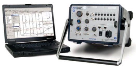
Benefits
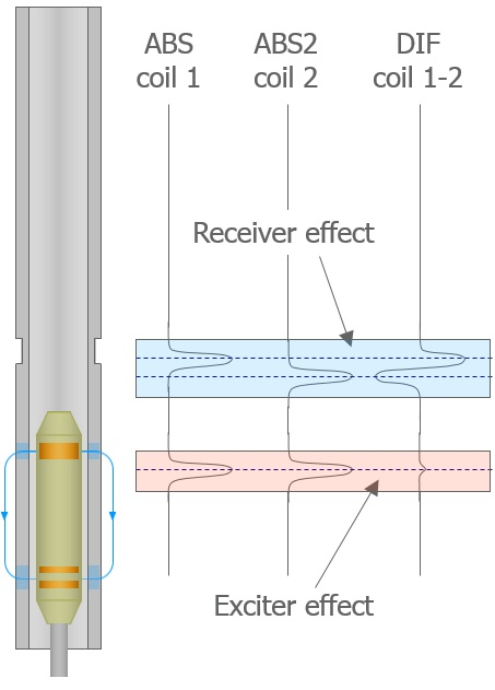
- Detecting common defects (corrosion, erosion, wear, pitting)
- Equally sensitive to ID & OD defects
- Inspection, typically 400 to 500 tubes per shift
- Good for general wall losses estimation. Limited sensitivity to pitting
- Computerized analysis
- Inspection of partially scaled tubes and boiler tubes with swages & bends
- Calibration tube required
- Cleanliness not as critical as IRIS or ECT. Faster than IRIS.
Magnetic Flux Leakage (MFL)
Introduction
The probe consists of one or two magnet and two flux leakage sensors, which set up a flux field in the tube wall as it passes through the tube. The field fluctuates when it encounters a flaw. The flux rate fluctuation effect is picked up by the coils and displayed on the display apparatus and chart recorder
Application
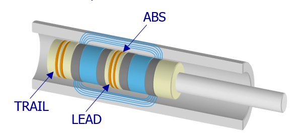

- Inspection of ferromagnetic tubes.
- The technique is used primarily as a screening tool
- Tubing in feed–water heaters, heat exchangers, boilers and piping
- Tube ID: 9.0mm – 76.2mm
- Tube Thickness: 0.7 – 6.0mm
Benefits
- Volumetric loss technique, capable of detecting internal and external defects
- Good for detecting pitting, poor wall thickness measurement capability.
- Inspection, typically 400–500 tubes per shift with preliminary analysis.
- Computerized analysis
- Calibration tube required
- IRIS backup essential in most cases
- Cleanliness is less critical than for IRIS